
RENUE — Make robots smarter
Supplier of welding seam positioning and welding seam tracking sensors
PRODUCT CATEGORIES
SV-BP series
Basic Size

Installation size
BP series smart sensors have three mounting surfaces, and the mounting dimensions and threaded hole sizes are shown in the figure:

Installation instructions
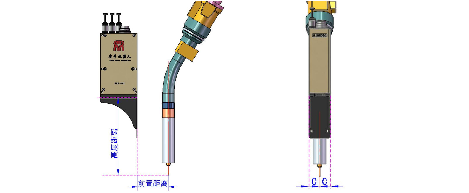
When installing BP series intelligent sensors, it is recommended to install them at the front end of the welding gun with extra distance (30~90mm). The sensor should be put to the welding gun as far as possible; In the vertical direction, the upright distance between the end of the welding wire and the bottom of the sensor msut be in the Viewable range, and it is recommended to be near the best visual distance (refer to Table 2: Sensor Model Selection Table (P11)); Horizontally, the welding gun has to be in the middle of the sensor.
1) When using the sensor for welding, it is recommended to install the sensor bracket in the flange, and do not install it on the welding gun. As a replaceable part, the welding gun may move or damage the sensor due to collision. Rt-sv2-bp series Installation and Maintenance Manual 6
2) The sensor bracket has good rigidity and will not generate deformation and vibration due to acceleration and deceleration of the robot; The sensor and bracket should be fixed well so that there will be no relative displacement due to the movement of the robot and the pulling of the cable.
3) The bottom of the arc baffle shall be lower than the connection line between the end of the sensor and the end of the welding wire to avoid direct spatters blocking the glass and affecting the identification of the sensor;
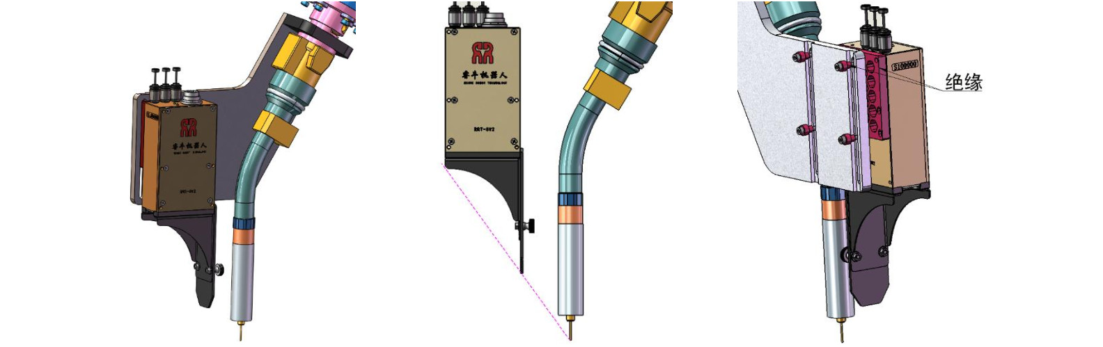
4) The sensor must be insulated, so the connection barrier between the sensor and the robot or other equipment must be made of insulating material (or part of the mounting bracket is insulated) (as shown in the figure).
Attachment: The picture below is a general fixture fixed on the welding gun selected by our company. It is only for debugging purposes and is forbidden to be used in actual welding.

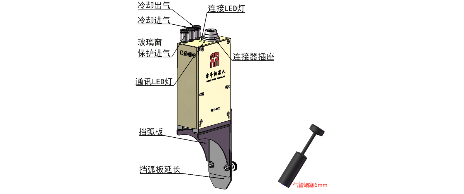
Cooling and glass window protection
There are two independent air channels inside the BP series smart sensor, including a cooling air inlet (CI) and a cooling air outlet (CO) for sensor cooling, as well as a circuit inside the sensor, and a glass window for glass window protection. Air port (SI) and its passage.
Note: When this function is not used, the air pipe joint cannot be left empty, and the air pipe can be blocked or sealed with tape
cooling system
For higher temperature environments, the sensor can be provided with suitable pressure and flow airflow to keep the sensor at a suitable working temperature.
Refer to the recommended parameters in the table below
| Trachea type | 6mm outside diameter trachea |
| Gas pressure | 0.3~0.6MPa |
| Gas flow | More than 30L/min |
Glass window protection
There is an air outlet at the bottom of the glass window, the continuous airflow reduces the pollution of dust and smoke to the lens.
Refer to the recommended parameters in the table below
| Trachea type | 6mm outside diameter trachea |
| Gas pressure | Less than 0.1MPa |
| Gas flow | 20 ~26L/min |
Note: 1. The protective gas of the glass window must be clean, dry and oil-free, otherwise a layer of oil may be formed on the glass, reducing the sensitivity of the vision system and affecting the sensor performance.
2. The gas flow rate is too high or too low will reduce the performance of the protective gas.
Power connection
Before use, insert the cable for power supply and data transmission of the sensor into the corresponding socket, and tighten the nut. When installing, ensure that the cable above the sensor is properly supported and fixed with a space for movement, and that there is no tensile stress on the cable when the sensor is moved. Otherwise, it may cause the sensor to move and affect the visual performance, and seriously damage the sensor or cable.
When laying out the cable, it should meet the minimum bending radius requirement, that is, the minimum bending radius should not be less than 10 times its outer diameter.
Sensor LED light
BP series smart sensors are equipped with two LED indicators. The green light is the network hardware connection LED light. The green light is always on after the sensor is powered on. Otherwise, there is a problem with the communication box and the sensor's hardware path, which needs to be eliminated first; the yellow light is the network data interaction LED light. The yellow light occasionally flashes to indicate that there is no external device or sensor. Connected, the yellow light flashes frequently, indicating that the external device (computer or robot) and the sensor have data interaction.

working principle
The tail of the sensor is a very important part of the laser vision system. The laser emitter at the tail emits a line of laser light to hit the surface of the object, and then the image capturer inside the sensor captures diffuse reflection light through the lens at the tail. The distance between each location point and the sensor.
The light path at the bottom of the sensor must not be blocked, otherwise it will affect the laser emission and signal recovery and reduce the accuracy. Figure 11 shows the space required for the sensor to work normally.
Parameters and selection
| RRT- - SV2- -P BP | |||
 |
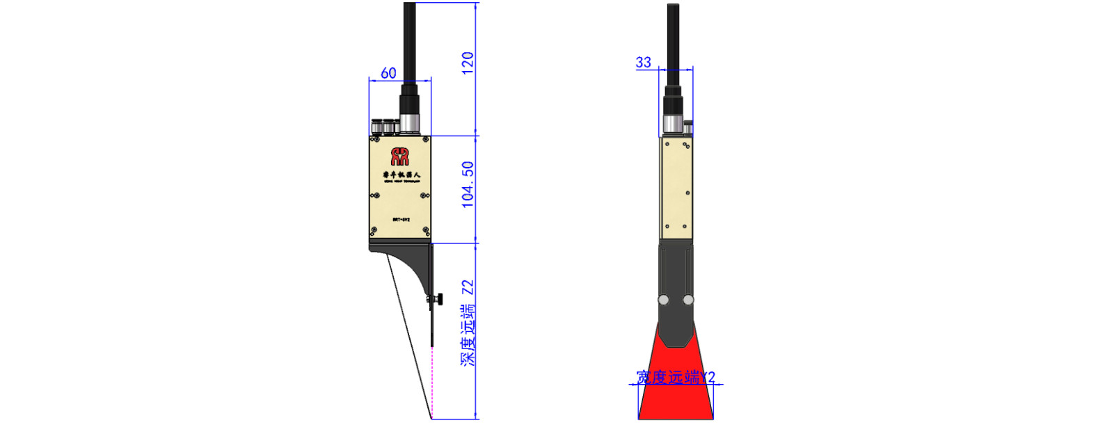
size | 104 4 .5* 60* * 33 mm | |
| weight | 378g | ||
| Frame rate | 30Hz | ||
| interface | 12pin aviation plug interface | ||
| communication | Types of | Ethernet N/CAN bus | |
| speed | Ethernet 1000M | ||
| power supply | Voltage | 9 ~ 32V | |
| Power consumption | 0.25A@24V | ||
| working environment | temperature range | 0 ~ 50℃ | |
| Humidity range | 10 ~ 95% without condensation | ||
| laser | Spot shape | Linear | |
| wavelength | 650nm | ||
| Power rating | IIIB | ||
| welding | Adaptability | Anti-reflection/ / Anti-arc interference Anti-splash/ / Anti-electromagnetic interference |
|
| Types of | Lap / / butt / / corner connection, etc., support customization | ||
| Applicable process | MAG/MIG/TIG/ | ||
| Table 1 Parameters | |||
The visual range, laser width and accuracy of each sensor are different, you can select the appropriate sensor according to the requirements according to the following table.
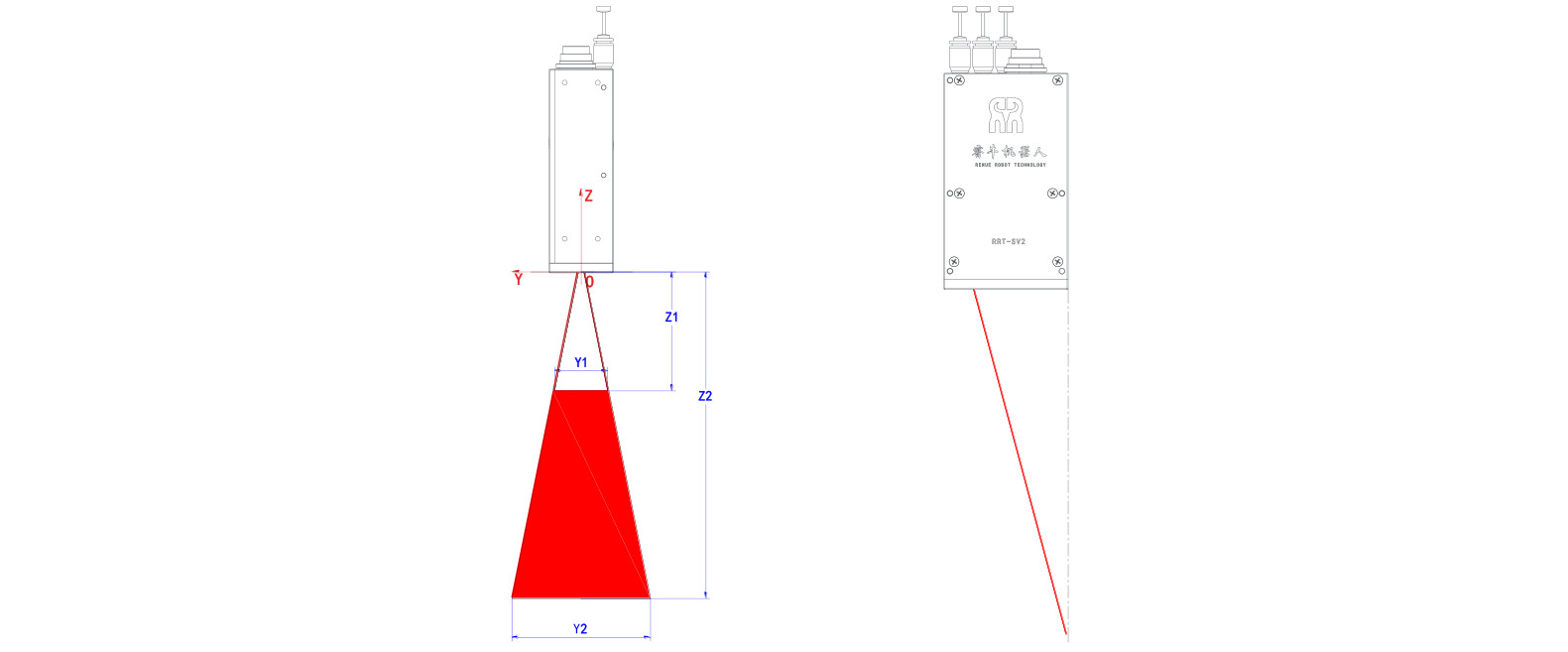
| model | Best viewing distance | Depth direction | Width direction | ||||
| Near end Z1 | remote Z2 | Depth resolution | Near end Y1 | remote Y2 | Width resolution | ||
| RRT- - SV2- - BP- -120 | 120 | 70 | 170 | 0.04~0.2 | 25 | 60 | 0.04~0.08 |
| RRT- - SV2- - BP- -120K | 120 | 70 | 170 | 0.04~0.2 | 50 | 110 | 0.04~0.1 |
| RRT- - SV2- - BP- -120Z | 120 | 70 | 170 | 0.02~0.1 | 18 | 37 | 0.02~0.05 |
Sensor model selection table
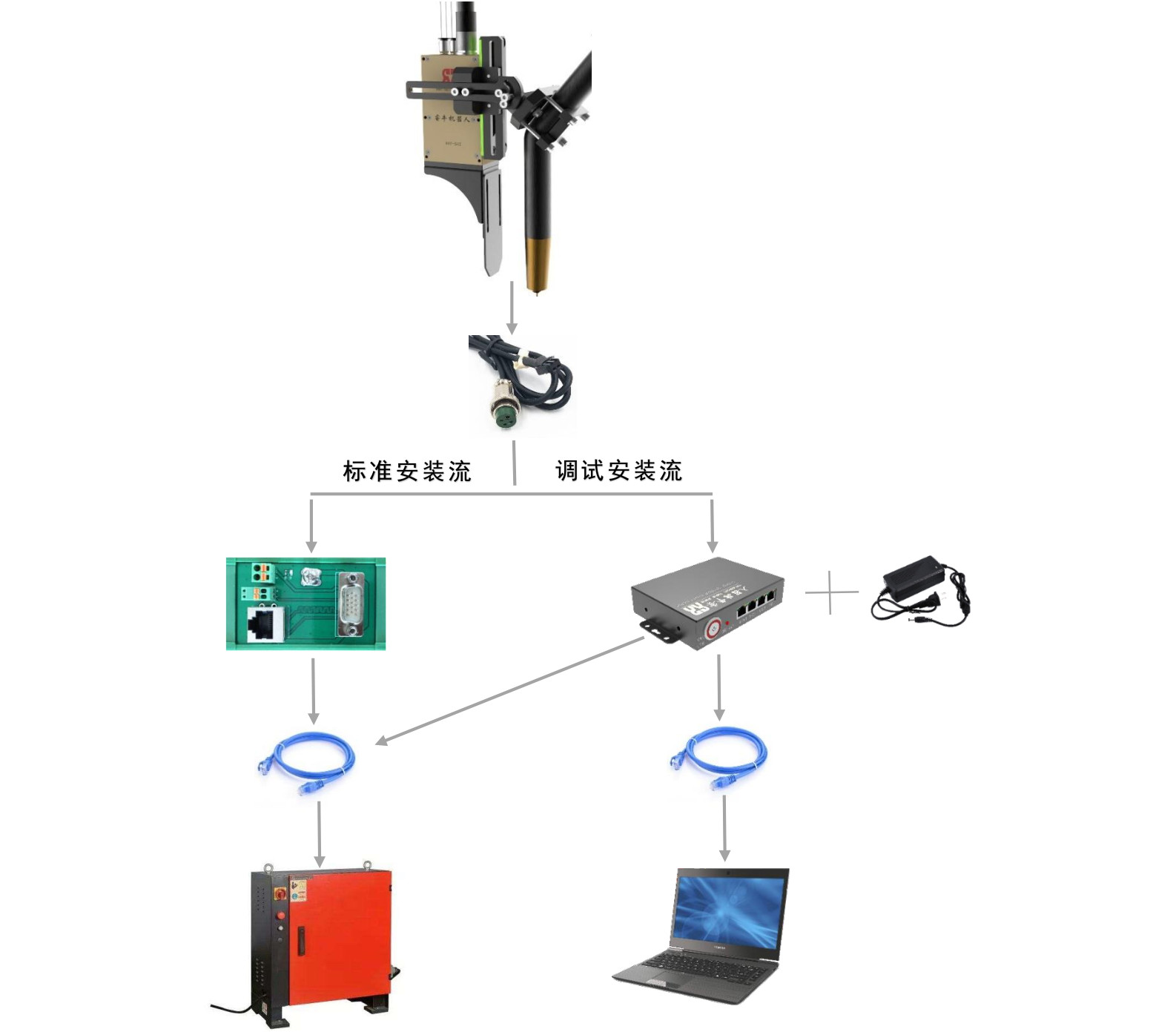
Installation process
BP series intelligent sensor and robot (computer) installation process reference diagram
Replace protective glass
The protective glass of the BP series smart sensor can prevent the optical components from accumulating soot and protect the optical components well. During use, the air inlet is protected by the glass window and blown out from the glass surface, which greatly reduces the accumulation of smoke and dust on the glass surface.
In order to use the sensor safely and reliably, it is recommended to check the protective glass daily and remove it for cleaning or replacement regularly. Replacing the protective glass: press the finger as shown, and pull out the contaminated glass; then insert the clean glass in the same way (as shown in the figure).
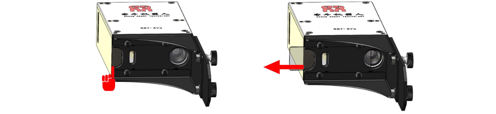
Note: 1. The laser hurts the eyes. When replacing the glass, the laser must be turned off.
2. When replacing the glass, make sure that there are no finger marks or stains on the glass at the laser exit and receiving window.

save
The RRT-SV2-BP series of smart sensors should be stored at a temperature of 0℃-60℃; the sensor should be stored in a clean, sealed and equipped with a desiccant environment to prevent condensation of internal components, and sudden temperature changes will also cause condensation Lu, also avoid this situation.

Weld tracking is no worry, Go to renue when in trouble!
ADD:Haosheng Industrial Park, Kunshan, Suzhou
TEL:0512-80171802 / 0512-80171805
PHONE:MR. 18626329319
E-MAIL:zhangxiangfeng@renue.com.cn
FAX:0512-80171801
WEB:www.renue.com.cn
Copyright © 2020 Suzhou Renue Robot Technology Co.,Ltd. All rights reserved 苏ICP备18033221号-1


